Good evening friends welcome back to my website. In my last post, I continued Theory of weight transfer by writing upon Anti-dive and Anti-squat geometry. Today, I would be taking you further by writing upon anti- roll Geometry, roll height centre and their significance in vehicle performance and stability. But before I write upon these there is some important piece of information to share with you all. Mechanical and Automobile Department of Madhav Institute of Technology and Science (MITS), Gwalior is organizing a workshop on Vehicle dynamics on 25-26th September under MPCST (Madhya Pradesh Council for Science and Technology) at college campus with a nominal fees of Rs.150/- for SAE members and Rs.200/- for non-SAE Members per event. And after this event, MITS is organising dy’signo 3.0 and cypher 3.0 for the third time under SAE India with a fee of Rs. 100/- per team per event on 15th October. Persons interested may contact me for further more information.
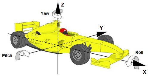
So, now let us start with today’s discussion. Rolling is the motion of vehicle which tends to rotate the vehicle due on cornering (due to centripetal force) or during one side bumps (Reactions of tyres). The rolling is more prevalent phenomena than pitching, therefore, more emphasis is given on rolling moment than pitching. So, to reduce the body roll what we do is position roll centre such that the distance between roll centre and centre of gravity of the vehicle is minimised. So, next question arises how one could minimise this distance? The answer lies in the arrangement of suspension geometry. For understanding this better lets us see how one finds out the position of roll centre.
So, now let us start with today’s discussion. Rolling is the motion of vehicle which tends to rotate the vehicle due on cornering (due to centripetal force) or during one side bumps (Reactions of tyres). The rolling is more prevalent phenomena than pitching, therefore, more emphasis is given on rolling moment than pitching. So, to reduce the body roll what we do is position roll centre such that the distance between roll centre and centre of gravity of the vehicle is minimised. So, next question arises how one could minimise this distance? The answer lies in the arrangement of suspension geometry. For understanding this better lets us see how one finds out the position of roll centre.
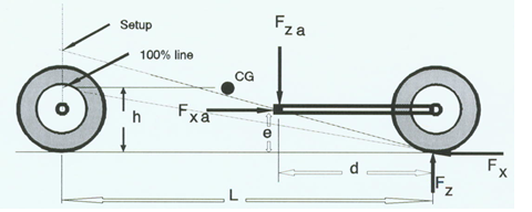
| If you have ready my previous post you would find the process similar to finding the percentage of anti-dive. So, to find roll centre take a front view of the car for front geometry and then identify the position of suspension arms under initial compression state. Draw lines passing through suspension arms and a hard point on chassis as shown in the figure. These two lines intersect at a point that point is called instantaneous centre of rotation of suspension arms. Through instantaneous centre draw a tangent to the tire of the vehicle. This tangent where ever cuts the vertical line of the centre of gravity that point will be called as roll centre of the vehicle. |  |
Now you see changing the positions of suspension hard points would alter the position of roll centre. I will be writing in more details when I would be covering Suspension’s geometry and their effects. But that may not be possible all times due to various limitations imposed on us by performance and comfort parameters of the vehicles. So, what more we can do to prevent rolling? The second thing we could do is use progressive spring instead of linear spring. So, how does progressive spring helps? The answer is simple during rolling left to right, the right side of spring compresses and left one expands. If you use linear spring force with compression from one side to cancelled by force on another side by spring expansion. But in the case of progressive force have a parabolic relation which tends to prevent rolling by providing greater force component on the right side, thus prevents rolling. But progressive springs are usually expensive to design and manufacture than linear spring.
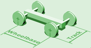
| The third option you have which is most common in today’s automobile industry is the use of anti-roll bars. This is most popular due to its effectiveness and low cost with desired performances in common vehicles. These anti-roll bars are the member which runs from one side of the car to other side connecting both sides of suspension. This prevents rolling in the way by preventing complete independent motion of the suspensions system on one side of the car. Anti-roll bars are now an integral part of modern buses, trucks, SUV’s and Trains too. This is the reason why high-speed turns are easily completed by high-speed trains because they employ anti-roll bars as their essential component of suspension. Now how they work. | 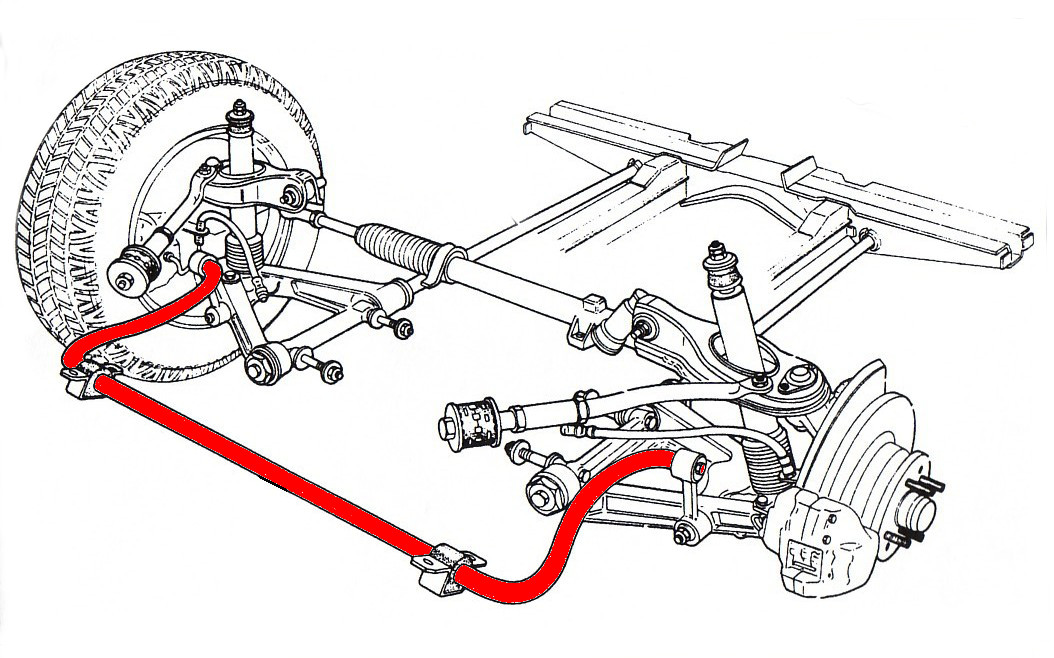 |
An anti-sway or anti-roll bar is intended to force each side of the vehicle to lower, or raise, to similar heights, to reduce the sideways tilting (roll) of the vehicle on curves, sharp corners, or large bumps. With the bar removed, a vehicle's wheels can tilt away by much larger distances. Although there are many variations in design, a common function is to force the opposite wheel shock absorber, spring or suspension rod to lower, or raise, to a similar level as the other wheel. In a fast turn, a vehicle tends to drop closer to the outer wheels, and the sway bar soon forces the opposite wheel to also get closer to the vehicle. As a result, the vehicle tends to "hug" the road closer in a fast turn, where all wheels are closer to the body. After the fast turn, then the downward pressure is reduced, and the paired wheels can return to their normal height against the vehicle, kept at similar levels by the connecting sway bar.
Because each pair of wheels is cross-connected by a bar, the combined operation causes all wheels to generally offset the separate tilting of the others and the vehicle tends to remain level against the general slope of the terrain. A negative side-effect of connecting pairs of wheels is that a jarring or bump to one wheel tends to also jar the opposite wheel, causing a larger impact applied across the whole width of the vehicle. A vehicle that runs over several potholes scattered on the road tends to rock side-to-side, or waddle, due to the action of the bar at each pair of wheels. Other suspension techniques can delay or dampen this effect of the connecting bar, as when hitting small holes that momentarily jolt a single wheel, whereas larger holes or longer tilting then tugs the bar with the opposite wheel.
Because each pair of wheels is cross-connected by a bar, the combined operation causes all wheels to generally offset the separate tilting of the others and the vehicle tends to remain level against the general slope of the terrain. A negative side-effect of connecting pairs of wheels is that a jarring or bump to one wheel tends to also jar the opposite wheel, causing a larger impact applied across the whole width of the vehicle. A vehicle that runs over several potholes scattered on the road tends to rock side-to-side, or waddle, due to the action of the bar at each pair of wheels. Other suspension techniques can delay or dampen this effect of the connecting bar, as when hitting small holes that momentarily jolt a single wheel, whereas larger holes or longer tilting then tugs the bar with the opposite wheel.
Thank you, everyone, for reading the post. If you do like my post click on like and share plus you could follow my blog on my official website http://vehicledynamics.weebly.com or on quora through http://vehicledynamics.quora.com . And if you have any complaints, suggestions, query or just simply want me to write something please feel free to use the comment box.