Good evening friends and welcome back to my website. In the last post, I have started weight transfer theory in vehicles. So, continuing the topic today I would be writing about how to design effectively suspension systems so that you could probably get out the desired performance of the vehicle. So, today we are going to cover one of its aspects that are anti-squat and anti-dive geometry or if combined then called anti-pitching geometry.
So, what are the two terms means both of the terms refers to the pitching motion of the vehicle due to weight transfer in rear and front during acceleration and braking respectively. Mathematically we find out the percentage of anti-squat and anti-dive to find out the degree to which vehicle have pitching motion due to weight transfer. The next question arises how do I calculate the percentage of anti-squat and anti-dive? What are the significance of this percentage on vehicles performance and driver’s comfort? The answer is given in the following paragraph.
So, what are the two terms means both of the terms refers to the pitching motion of the vehicle due to weight transfer in rear and front during acceleration and braking respectively. Mathematically we find out the percentage of anti-squat and anti-dive to find out the degree to which vehicle have pitching motion due to weight transfer. The next question arises how do I calculate the percentage of anti-squat and anti-dive? What are the significance of this percentage on vehicles performance and driver’s comfort? The answer is given in the following paragraph.
| For the answer to the first question refer to the figure on your right. It is the side view of the car showing the calculation of anti-squat geometry for the rear wheel. To find the percentage of anti-squat what we do is first find out the instantaneous center of pitching motion of the sprung mass which is founded out by the line coming from suspension hard points i.e. where the suspension is mounted on the chassis. | 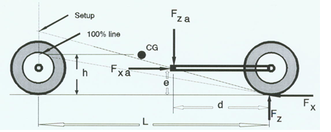 |
The intersection of the lines coming out of the suspension arms gives the instantaneous centre of the pitching motion. (In the figure since suspension arm is one, therefore, it has instantaneous centre at hard point itself) Now draw a tangent to the tyre of the wheels which passes through the instantaneous centre as shown in the figure. This line intersects with the vertical lines from Centre of gravity then the obtained point is called pitch centre and the ratio of the height of the pitch centre from the ground to the height of the Center of gravity is called anti-squat or anti-dive percentage.
Now answer to the next question what does it signify? A 100% anti-dive geometry means there would be no pitching motion of the vehicle which would mean all load due to weight transfer will be bear by suspension arms which results in the decrease in the level of comfort of the driver. Usually, 0-50% of anti-dive and anti-squat is provided in modern cars. The lower number range is for the drag racers as they wish to promote weight transfer to improve traction and of tyres for improved acceleration and deacceleration whereas upper limit is for the common passenger car and loading vehicles as nobody wants to drive a car which would go 5 inches down on applying brakes especially in traffic region. One more thing you must remember suspension springs must be capable of carrying and resisting the load increase due to weight transfer. So, you may have to increase the stiffness of the spring for getting desired anti-squat percentage.
In my next post I would be continuing this topic by writing upon anti-rolling geometry.
Thank you, everyone, for reading the post. If you do like my post click on like and share plus you could follow my blog on my official website http://vehicledynamics.weebly.com or on quora through http://vehicledynamics.quora.com . And if you have any complaints, suggestions, query or just simply want me to write something please feel free to use the comment box.
